VFD Frequency to Motor RPM: Calculation & Speed Chart
Calculate motor speed from VFD frequency across 2, 4, 6, and 8-pole motors. Includes slip calculations, constant torque limits, and frequency tables.
When programming an industrial variable frequency drive or troubleshooting an automated production line, converting drive output frequency into exact motor shaft RPM is critical. Guessing shaft speeds without accounting for pole counts and rotor slip causes equipment jamming and motor overheating. The formula to calculate motor speed from VFD frequency is (120 × f) / p × (1 - s). Here is the complete engineering guide and frequency speed chart.
A Variable Frequency Drive (VFD) regulates electric motor velocity by modulating both output voltage and frequency. Because synchronous speed depends directly on the supplied alternating current waveform frequency, altering Hertz proportionally changes motor shaft speed.
You can calculate custom operating points using the interactive calculator below, or review our reference library of standard drive ratios in the conversions directory:
The Core Formula: Frequency to Synchronous RPM
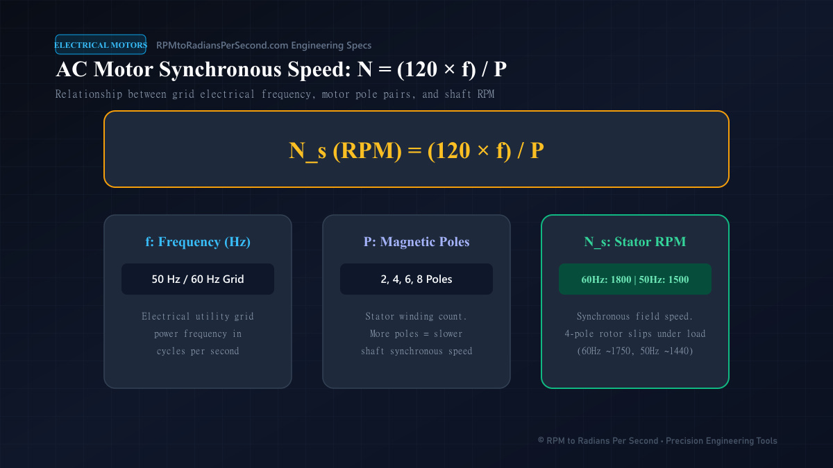
The fundamental equation governing AC induction and synchronous motor speed stems from the number of magnetic poles wound into the stator. Standard motor performance specifications published by the National Electrical Manufacturers Association (NEMA) alongside research from the IEEE define this baseline:
N_s = (120 × f) / pWhere:
- N_s is synchronous speed in revolutions per minute (RPM).
- f is VFD output frequency in Hertz (Hz).
- p is the physical quantity of magnetic stator poles (must be an even integer: 2, 4, 6, 8, etc.).
- 120 is the dimensional constant converting seconds to minutes while adjusting for pole pairs.
For a standard 4-pole motor operating at a baseline frequency of 60 Hz, the synchronous speed is (120 × 60) / 4 = 1800 RPM. If the VFD reduces output frequency down to 30 Hz, synchronous speed drops linearly to (120 × 30) / 4 = 900 RPM. For deeper context on native line-frequency baselines, consult our guide on standard motor RPMs.
Comprehensive VFD Frequency to Motor RPM Chart
The table below outlines synchronous shaft speeds across standard VFD output frequencies for 2, 4, 6, and 8-pole motors:
| VFD Frequency (Hz) | 2-Pole Motor (RPM) | 4-Pole Motor (RPM) | 6-Pole Motor (RPM) | 8-Pole Motor (RPM) |
|---|---|---|---|---|
| 10 Hz | 600 RPM | 300 RPM | 200 RPM | 150 RPM |
| 20 Hz | 1,200 RPM | 600 RPM | 400 RPM | 300 RPM |
| 30 Hz | 1,800 RPM | 900 RPM | 600 RPM | 450 RPM |
| 40 Hz | 2,400 RPM | 1,200 RPM | 800 RPM | 600 RPM |
| 50 Hz | 3,000 RPM | 1,500 RPM | 1,000 RPM | 750 RPM |
| 60 Hz (Base) | 3,600 RPM | 1,800 RPM | 1,200 RPM | 900 RPM |
| 70 Hz | 4,200 RPM | 2,100 RPM | 1,400 RPM | 1,050 RPM |
| 80 Hz | 4,800 RPM | 2,400 RPM | 1,600 RPM | 1,200 RPM |
| 90 Hz | 5,400 RPM | 2,700 RPM | 1,800 RPM | 1,350 RPM |
| 120 Hz | 7,200 RPM | 3,600 RPM | 2,400 RPM | 1,800 RPM |
Notice that at 120 Hz, a 4-pole motor operates at 3,600 RPM—identical to the speed of a 2-pole motor at 60 Hz. For an analysis of how cycles per second relate to mechanical revolutions, read our technical overview of rpm to hz.
Accounting for Rotor Slip in Induction Motors
The synchronous speed values in the chart above represent the speed of the rotating magnetic stator field. Squirrel-cage induction motors cannot develop torque unless the physical rotor lags slightly behind this field.
This relative difference is called rotor slip:
s = (N_s - N_r) / N_sWhere:
- s is the dimensionless slip fraction (typically 0.02 to 0.05 at full load).
- N_s is synchronous speed in RPM.
- N_r is actual shaft speed in RPM.
To calculate true shaft speed under mechanical load, apply the slip correction factor:
N_r = ((120 × f) / p) × (1 - s)For example, a 4-pole motor running at 45 Hz with 3% full-load slip operates at:
N_r = ((120 × 45) / 4) × (1 - 0.03) = 1,350 × 0.97 = 1,309.5 RPMTo verify nameplate baseline ratings at full synchronous speed, review our dedicated guide on 1800 rpm to rad/s.
Constant Torque vs. Constant Horsepower Regions
Operating a motor above its base nameplate frequency (typically 60 Hz in North America or 50 Hz in Europe) fundamentally alters drive performance characteristics.
The Constant Torque Region (0 to 60 Hz)
Between zero and base frequency, the VFD maintains a constant Volts-per-Hertz (V/f) ratio. For a 460V, 60 Hz motor, this ratio is 460 / 60 = 7.67 V/Hz. By maintaining constant magnetic flux density in the stator core, the motor produces its full rated torque across this entire frequency window. Horsepower rises linearly with RPM:
P = τ × ωTo review how electrical current draws scale under varying voltage and load regimes, consult our electrical motor amp chart.
The Constant Horsepower / Field-Weakening Region (Above 60 Hz)
Once the VFD reaches maximum output voltage (e.g., 460V at 60 Hz), it cannot supply additional voltage as frequency continues to climb. The drive enters field weakening, where magnetic flux weakens inversely with frequency.
Shaft torque decreases inversely with speed, while available mechanical horsepower remains flat. Operating above rated speeds also risks bearing over-speed damage and excessive centrifugal stress. To calculate horsepower and torque curves across varying speeds, read our resource on rpm and torque to horsepower.
Practical Sizing: Conveyor Speed at Varying VFD Frequencies
In automated packaging and manufacturing plants, engineers routinely adjust VFD frequencies to control line transport speeds. Connecting motor shaft speed through a speed reducer to a conveyor drive roller requires tracking both the gear ratio and roller circumference.
For a 4-pole motor driving a 10:1 gearbox with a 200 mm (0.20 m) diameter drive drum:
| VFD Frequency | Motor RPM (3% Slip) | Gearbox Output RPM | Drum Surface Speed (m/s) | Conveyor Speed (ft/min) |
|---|---|---|---|---|
| 15 Hz | 436.5 RPM | 43.65 RPM | 0.457 m/s | 89.9 FPM |
| 30 Hz | 873.0 RPM | 87.30 RPM | 0.914 m/s | 179.9 FPM |
| 45 Hz | 1,309.5 RPM | 130.95 RPM | 1.371 m/s | 269.8 FPM |
| 60 Hz | 1,746.0 RPM | 174.60 RPM | 1.828 m/s | 359.8 FPM |
For detailed equations connecting gearbox reductions and roller diameters to linear surface velocities, refer to our guides on gear ratio rpm calculator and rpm to linear velocity.
Python Calculation Script for Automation Engineers
Industrial automation platforms and telemetry scripts calculate motor speed continuously from PLC frequency registers. University course materials, such as those provided by MIT OpenCourseWare, highlight the importance of structured calculations in digital drive models.
def calculate_motor_rpm(frequency_hz: float, poles: int, slip_percent: float = 0.0) -> float:
    if poles % 2 != 0 or poles <= 0:
        raise ValueError("Poles must be a positive even integer.")
    synchronous_rpm = (120.0 * frequency_hz) / poles
    rotor_rpm = synchronous_rpm * (1.0 - (slip_percent / 100.0))
    return rotor_rpm

freq = 45.0
motor_poles = 4
slip = 2.8 # 2.8% slip under load

speed = calculate_motor_rpm(freq, motor_poles, slip)
print(f"Shaft Speed: {speed:.2f} RPM") # Output: 1312.20 RPM
Frequently Asked Questions
How do I calculate motor RPM from VFD frequency?
Multiply VFD frequency by 120 and divide by the number of motor poles: RPM = (120 × f) / p. To account for full-load slip, multiply the result by (1 - slip).
What speed does a 4-pole motor run at 30 Hz?
On a 4-pole motor, synchronous speed at 30 Hz is (120 × 30) / 4 = 900 RPM. Under typical mechanical load with 3% slip, the rotor spins at approximately 873 RPM.
Can you run a 60 Hz motor at 75 Hz on a VFD?
Yes, provided the motor and mechanical load are rated for over-speed operation. However, the drive operates in the field-weakening zone above 60 Hz, meaning available shaft torque decreases as speed increases.
Why does my motor overheat when running slowly on a VFD?
Standard TEFC motor cooling fans are mounted to the motor shaft. At frequencies below 30 Hz, fan speed drops, drastically reducing cooling airflow while the motor continues to draw high current under load.
What is the difference between synchronous speed and actual rotor speed on a VFD?
Synchronous speed is the rotational velocity of the stator magnetic field. Actual rotor speed is the physical shaft speed, which is 2% to 5% slower in induction motors to induce the electrical current necessary to produce torque.
Ready to run the numbers?
Get your result instantly — private, in your browser.