RPM to Angular Velocity Radians Per Second: Vector Guide
Translate RPM into angular velocity radians per second. Master 3D rotational vectors, gyroscopic precession, right-hand rules, and rotor dynamics.
You have mastered translational velocity, but your engineering project suddenly introduces rotating coordinate systems and spinning shafts. The hardware tachometer reads in RPM, yet your kinematic equations demand angular velocity as an exact vector in radians per second. Treating angular velocity as a simple unscaled scalar causes catastrophic coordinate transformations, inverted cross products, and broken control loops. The solution is straightforward: translate RPM into radians per second using our interactive vector tool below.
Beyond Tachometer Readings: The Vector Nature of Angular Velocity
When engineers talk about translating rpm to angular velocity radians per second, they are making a profound physical jump from a scalar frequency to a directional spatial vector.
Revolutions Per Minute (RPM) is a scalar quantity indicating how many 360-degree cycles a shaft completes over sixty seconds. It tells you how rapidly a wheel spins, but reveals nothing about its spatial orientation or rotation axis.
By contrast, angular velocity (denoted by the lowercase Greek letter ω) is a true pseudovector in three-dimensional space:
ω = [ω_x, ω_y, ω_z]^T = ω · n̂According to standards maintained by the Bureau International des Poids et Mesures (BIPM) and the National Institute of Standards and Technology (NIST), the coherent SI unit for angular velocity is the radian per second (rad/s). To convert scalar RPM into vector magnitude:
|ω| (rad/s) = RPM × (2π / 60) = RPM × (π / 30)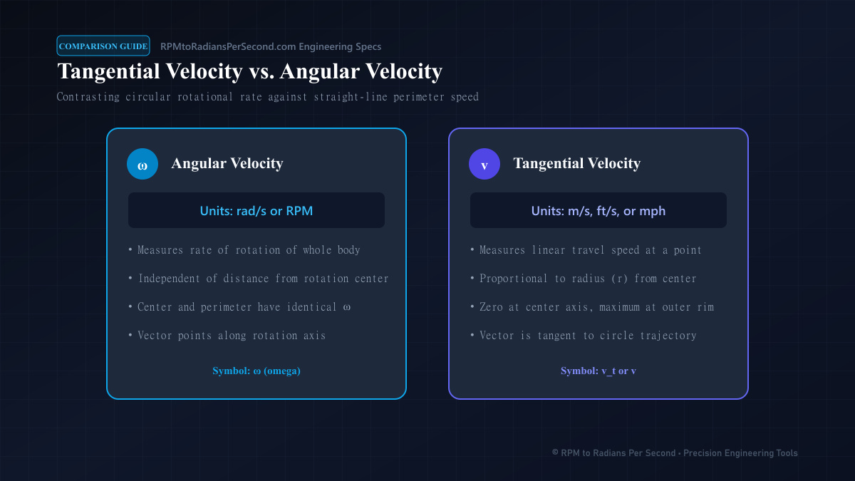
Cross Products and Tangential Velocity in 3D Space
The primary reason vector kinematics requires angular velocity in radians per second is the evaluation of spatial cross products. In a rigid rotating body, every particle experiences an instantaneous translational velocity determined by its position vector (r):
v = ω × rThis fundamental vector equation is only mathematically valid when ω is expressed in radians per second:
- Magnitude Calculation: The scalar magnitude is , where is the angle between the rotation axis and the position vector.
- Directional Orthogonality: The resulting velocity vector v is mutually perpendicular to both the rotation axis ω and the radial displacement r.
- No Conversion Coefficients: Expressing angular rate in rad/s eliminates arbitrary trigonometric conversion constants from the matrix determinant.
If you plug RPM directly into a vector cross product, your calculated linear speed will be overstated by a factor of . To compute tangential speeds for robotic end-effectors, consult our rpm to linear velocity guide.
Gyroscopic Precession: Rotational Inertia in Moving Frames
When a high-speed rotor experiences an external torque perpendicular to its spin axis, it does not tilt in the direction of the applied force. Instead, it precesses at a right angle.
This gyroscopic behavior is governed by the angular momentum vector (L):
L = I · ωWhere I represents the rotor's mass moment of inertia tensor. When an external pitch torque () is applied to the spinning assembly, the axis precesses with an angular velocity ():
τ = Ω_p × L = Ω_p × (I · ω)In marine gyro-stabilizers, aircraft jet turbines, and spacecraft reaction wheels, control computers convert turbine RPM directly into rad/s to predict precession forces. Sizing gimbal bearings without exact radian-per-second momentum modeling results in mechanical bearing fatigue and housing rupture.
| Rotating Assembly | Typical Speed (RPM) | Exact Vector Magnitude | Decimal Velocity (rad/s) | Dominant Kinematic Effect |
|---|---|---|---|---|
| Reaction Wheel (Satellite) | 6,000 RPM | 200π rad/s | 628.32 rad/s | Precision attitude control torque |
| Helicopter Main Rotor | 400 RPM | 40π/3 rad/s | 41.89 rad/s | Aerodynamic lift & gyroscopic flap |
| High-Speed Turbocharger | 150,000 RPM | 5,000π rad/s | 15,707.96 rad/s | Extreme centrifugal stress & whirling |
| Precision Inertial Gyro | 24,000 RPM | 800π rad/s | 2,513.27 rad/s | High angular momentum drift rejection |
| Direct-Drive Wind Turbine | 12 RPM | 2π/5 rad/s | 1.26 rad/s | Massive structural torque absorption |
Rotating Reference Frames: Coriolis and Centrifugal Forces
In dynamic simulations of rotating mechanisms (such as centrifuge arms, fluid pumps, or planetary rovers), equations of motion are evaluated within a rotating coordinate frame.
According to classical mechanics codified by the American Society of Mechanical Engineers (ASME), transforming accelerations from an inertial frame to a rotating frame introduces fictitious forces:
a_inertial = a_rotating + 2(ω × v_rel) + ω × (ω × r) + (dω/dt × r)Each term in this kinematic expansion depends strictly on angular velocity in radians per second:
- Coriolis Acceleration (2ω × v_rel): Acts perpendicular to particle motion within the rotating frame, driving fluid vortices in industrial centrifuges.
- Centripetal Acceleration (ω × (ω × r)): Directs inward toward the rotation axis, generating centrifugal separation force. For laboratory separation protocols, explore our centrifuge rpm to rcf guide.
- Euler Acceleration (dω/dt × r): Arises during rotational acceleration or deceleration when motor speed changes over time.
Dynamic Torque Sizing: Angular Acceleration (Torque = I · α)
Converting steady-state RPM to angular velocity (ω) is only the initial stage of dynamic mechanism design. Real-world machinery must accelerate from rest to operational speed within strict cycle times.
Angular acceleration (symbolized by α) represents the time rate of change of angular velocity, measured in radians per second squared (rad/s²):
α (rad/s²) = (ω_target - ω_initial) / ΔtAccording to Newton's Second Law for rotational systems, the required acceleration torque depends directly on the assembly's moment of inertia:
Torque_acc (N·m) = I × α = I × [ (RPM_target × π/30) / Δt ]Suppose an automation drive accelerates an indexing dial plate (inertia I = 0.85 kg·m²) from 0 to 1,200 RPM in exactly 0.40 seconds.
- First, convert 1,200 RPM into angular velocity:
1,200 × (π / 30) = 40π ≈ 125.66 rad/s. - Next, calculate angular acceleration:
125.66 / 0.40 = 314.16 rad/s². - Finally, compute acceleration torque:
0.85 kg·m² × 314.16 rad/s² = 267.04 N·m.
If the engineer improperly substituted raw RPM (1,200) into this dynamic formula, the computed torque would be 2,550 N·m—leading to specifying a motor nearly ten times larger than necessary! For steady-state electrical drive metrics, review our rpm and torque to horsepower calculator.
Critical Whirling Speeds and Rotor Dynamic Resonance
When designing high-speed rotating shafts for compressors, steam turbines, or machine tool spindles, machine speed cannot be increased arbitrarily without checking structural resonance.
Every elastic shaft possesses natural lateral bending frequencies determined by shaft stiffness () and distributed mass ():
Natural Bending Frequency ω_n (rad/s) = √(k_shaft / m_rotor)Because structural bending modes are calculated directly in radians per second, rotordynamicists map operational speeds against natural frequencies using Campbell diagrams. When operational angular velocity (ω) coincides with a natural bending frequency (ω_n), the rotor reaches its critical whirling speed:
Critical Speed (RPM) = ω_n × (30 / π)At this resonance threshold, residual unbalance forces amplify exponentially, causing excessive shaft deflection and bearing destruction. In rotating machinery conforming to ISO 1940-1 balance quality standards, Variable Frequency Drives are programmed with speed-exclusion bands to accelerate rapidly through critical speeds. To explore grid synchronous motor baselines, review our standard motor rpms guide.
When transitioning calculated angular velocities back into equipment procurement datasheets, use our reverse radians per second to rpm reference.
Frequently Asked Questions
1. Is angular velocity a scalar or a vector?
Angular velocity is a true spatial pseudovector. Its magnitude represents rotational rate in radians per second, and its direction defines the rotational axis following the right-hand rule convention.
2. Why does the vector cross product v = ω × r require rad/s?
The definition of the radian as a dimensionless arc-to-radius ratio () ensures that time differentiation yields linear velocity without extra dimensional conversion factors. Using RPM requires an extra coefficient in every cross product.
3. How do you convert 3D RPM into vector components?
Multiply scalar RPM by to determine vector magnitude , then multiply by the normalized unit direction vector along the shaft axis: ω_vec = |ω| · [n_x, n_y, n_z].
4. What happens if I reverse the direction of the angular velocity vector?
Reversing the vector direction signifies opposite rotation (clockwise versus counterclockwise). In matrix kinematics, flipping the vector sign reverses the calculated direction of all linear velocity and Coriolis acceleration vectors.
Designing multi-axis mechanisms or gyroscopic stabilization systems? Explore our interactive conversion library to compute exact π-based angular velocities, frequency harmonics, and linear travel metrics with zero rounding discrepancies.
Ready to run the numbers?
Get your result instantly — private, in your browser.